What is Limp Mode? – Causes & What to Do
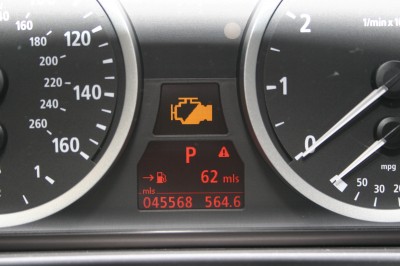
Picture this: you are driving along when, out of the blue, your car’s transmission starts acting up. The “check engine” light comes on, telling you that there is a problem. At the same time, your car’s transmission automatically shifts into second or third gear and stays there.
http://www.hallsautoonline.com/obd_ii_code_definitions.htm
Limited to one gear and 30-45 mph, you know there is a serious problem with your car’s transmission and you have to get your car to either your dealer or transmission repair shop to have the problem diagnosed and repaired.
Naturally, the first questions that go through your head are: Why did this happen? How severe is it? and How much will it cost to fix?
In This Guide
- What Causes Limp Mode?
- Limp Mode’s Protective Actions
- Example Situation
- How the Computer Determines That a Sensor is Incorrect
- What You Should Do
- Questions to Ask Yourself
What Causes Limp Mode?
Since the early 1980s, computers have been responsible for monitoring and controlling systems in automobiles. At first, the computer was used primarily for emissions control and fuel economy, but within a few years, many more systems were computer controlled included anti-lock braking, airbags, climate control and handling.
Today, nearly every system in your vehicle is operated by the computer – including the transmission’s line pressure, shift timing, sequence and feel. The vehicle speed sensor provides input to help control ABS, fuel mixture, fuel injection and transmission operation. The manifold absolute pressure (MAP) sensor and throttle position sensor (TPS) provide the engine’s load information which is used to manage the shift and downshifting in the transmission when you’re driving up an incline or you’ve put the pedal to the metal.
“Fail Code” conditions or “Limp Mode” occurs when there is a problem with the logic of a vehicle’s computer. When the signal value sent by a sensor to the computer is not within a pre-programmed range specified by the manufacturer, it will switch to “secondary” programming. These procedures are designed to protect the transmission from further damage that could be caused by the signal error.
As long as the computer is receiving signals from the MAP, TPS, vehicle speed and other sensors that fall within their “normal” ranges based on the current conditions, the transmission will operate normally. However, as mentioned above, if it receives a signal that is outside of the expected range, it will switch to secondary/emergency operation.
The exact measures taken in secondary operation is determined by the computer’s logic as programmed by the manufacturer and depends on how far outside the acceptable range the signal is (if there is any signal at all). It might react differently when the value is higher than the highest parameter than it does when the value is lower than the lowest allowable value.
Limp Mode’s Protective Actions
If the signal value wasn’t far enough outside of the range to indicate a mechanical failure, the first thing the computer will do is turn the check engine light on to alert the driver that they should have the vehicle checked out using a code reader/diagnostic scanner to see if there are any “soft codes” listed. Soft codes can indicate that a low priority sensor has malfunctioned or is starting to break down. If the light goes away after restarting your car, it could mean that the sensor only failed once due to a loose connection or it could be a sign that its condition is getting worse. Critical functionality is typically unaffected by this kind of problem, but if the issue isn’t resolved, it can negatively impact the performance or fuel efficiency of the vehicle.
Now, if the signal value from a high priority sensor (necessary for critical functions) is dangerously far out of the acceptable operating range, the computer switches over to secondary “survival” mode. This is known as a “hard code”. In this mode, the computer shuts off the electronic shift solenoids. This disables the transmission’s ability to shift gears and causes it to default to single usable gear – usually second or third. In addition, the pressure in the transmission’s fluid lines is set to high in order to protect the bands and clutches from being damaged. The signals that control the line pressure are set to “full on” to prevent the clutch pack from a slipping dangerously.
All of these changes result in the previously described “Limp Mode”. Instead of leaving you stranded with a broken down vehicle, it enables the vehicle to limp home or to the nearest service center for repairs while reducing the risk of doing further damage.
Example
For example, one of situations that would cause a transmission to go into limp mode is if the cable harness going to the transmission is damaged or detached. In this case, the computer would sense that it lost communication with the transmission, but since the harness is detached, the command to go into limp mode cannot make it to the transmission. However, with no power supplied to the solenoids, the line pressure is set to high and the transmission is stuck in 2nd or 3rd gear – the same effect the limp mode command would have.
How the Computer Determines That a Sensor is Incorrect
Say, for example, that the computer receives a signal from the Throttle Position Sensor (TPS) stating that the pedal is to the metal when the throttle is actually closed. It would spot this error when it compared this status with the vehicle speed sensor, which would be signaling low or no speed. As soon as it sees this discrepancy, the computer will command the transmission to go into limp mode and turn the check engine light on. A signal value by itself can’t always be classified as an error, but when analyzed with other sensor outputs, the computer can easily figure out if there is a problem.
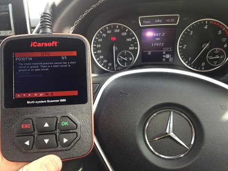
The fault code of the sensor causing the error is recorded by the computer. A mechanic can use a diagnostic scanner or code reader to find the recorded codes and then look them up in a table from the manufacturer to determine which sensor, and therefore which system is the source of the malfunction. Many scanners are pre-programmed with these tables and return more information than just the codes.
For example, the diagnostic scanner could return the code “35”, which indicates that the problem has to do with the transmission fluid temperature sensor. The abnormal values that were recorded and the “normal” range for the sensor could also be provided to the mechanic.
It is recommended to have a vehicle’s computer scanned regularly for fault codes – especially if the check engine light is on. This is done by most service centers during routine tune-ups.
What You Should Do
If your transmission is in limp mode, your transmission has a problem and you should get it fixed as soon as possible. Here is what you should do:
- Do not panic! Limp mode is specifically designed to limit further damage and allow you to get your car to a service center
- If possible, drive directly to a service center
- Otherwise, drive home and call a service center to have your vehicle towed
- If you do not feel comfortable driving at a limited speed, pull off the road where it is safe to do so and call for a tow
- It is advised that you do not continue to drive a vehicle in limp mode as it is unsafe and can cause further damage to your vehicle
Questions to Ask Yourself
Once your vehicle is safely in the service area, it is time to answer a few questions that will help diagnose the problem:
- How fast were you driving and how long had you been driving when the problem occurred?
- Did any lights on the dash come on? Did they come on when you started the car or after driving a while? Did they stay on?
- What repairs or maintenance has been done to the vehicle in the last month?
- Have you noticed any signs of a problem recently (noises, behaviors, leaks, etc.)?
_______________________________________________________________
P0068 MAP/MAF - Throttle Position Correlation OBD-II Trouble Code Technical Description Article by Don Bowman ASE Certified Automotive Tech MAP/MAF - Throttle Position Correlation What does that mean? This diagnostic trouble code (DTC) is a generic powertrain code. It is considered generic because it applies to all makes and models of vehicles (1996-newer), although specific repair steps may be slightly different depending on the model. The generic trouble code P0068 refers to an engine management problem. A disparity exists between the computer's sensors as to the volume of air entering the intake manifold. The PCM relies on three sensors to indicate air flow volume in order to calculate fuel and timing tactics. These sensors include the mass airflow sensor, throttle position sensor and the Manifold pressure (MAP) sensor. There are many sensors on the engine however these are the three associated with this code. The mass airflow sensor is located between the air cleaner and the throttle body. Its job is to signal the amount of air passing through the throttle body. In order to accomplish this, a thin piece of resistance wire the thickness of a hair stretches across in the inlet of the sensor. The computer sends voltage to this wire to heat it to a predetermined temperature. As air volume increases it requires more voltage to maintain the temperature. Conversely, it requires less voltage as the air volume drops. The computer recognizes this voltage as an indication of air volume. The throttle position sensor rests on the opposite side of the throttle plate in the throttle body. When closed, the throttle plate prevents airflow into the engine. Air necessary for idle bypasses the throttle valve by way of an idle air control motor. Most later model vehicles use a throttle position sensor on the floorboards at the top of the gas pedal. As the pedal is depressed the sensor attached to the pedal sends a voltage to an electric motor that controls the opening of the throttle plate. In operation, the throttle position sensor is nothing more than a rheostat. With the throttle plate closed at idle, the throttle position sensor registers very close to 0.5 volts and when opened as in accelerating, the voltage will rise to approximately 5 volts. The transition from 0.5 to 5 volts should be very smooth. The engine's computer recognizes this increase in voltage as a signal indicating the amount of airflow and rate of opening. The Manifold Absolute Pressure (MAP) has a dual role in this scenario. It senses the manifold pressure corrected for air density due to temperature, humidity and altitude. It is also linked to the intake manifold through a hose. When the throttle suddenly opens the manifold pressure drops just as sudden and rises again as the air flow increases. The engine management computer requires all three of these sensors to accurately strategize the length of time to open the injectors and how much spark advance is necessary to maintain a 14.5/1 fuel ratio. If, for some reason one of these sensors or a mechanical problem causes a disparity between the rest, the computer is incapable of making the proper adjustments and sets the P0068 trouble code. Symptoms The symptoms displayed for a P0068 code will depend on the cause of the overboost condition: The service engine soon or check engine light will illuminate. Rough running engine - the computer will set the above code and additional codes depicting the faulty sensor if the problem is electrical.Without the correct airflow the engine will develop a rough idle, and depending on the severity, it may not accelerate or have a serious dead spot off idle. In short, it will run lousy Causes Potential causes for this DTC include: Vacuum leaks between the mass airflow sensor and intake manifold and loose or cracked hoses Dirty air cleaner Leak in the intake manifold or sections Faulty sensor Coked intake runner behind throttle body Poor or corroded electrical connectors Obstruction to air flow Defective electronic throttle body Obstruction in hose from intake manifold to MAP sensor Diagnostic Steps & Possible Solutions Like an auto technician, start with the most common problems. You will need a volt/ohmmeter, wire-piercing probe for the meter, a can of carburetor cleaner and a can of intake cleaner. Repair any problems as they are found and start the vehicle to determine if the problem is corrected -- if not continue the procedures. With the engine off, open the hood and check the air cleaner element. Look for any loose clamps or leaks in the piping from the mass airflow sensor to the throttle body. Inspect all the vacuum lines on the intake manifold for obstructions, cracks or looseness which could cause loss of vacuum. Disconnect each of the sensors and check the connector for corrosion and pushed out or bent pins. Start the engine and use the carburetor cleaner to find any leaks in the intake manifold. A short shot of carburetor cleaner over a leak will change the engine rpm noticeably. Hold the can at arms length to keep the spray from contacting your eyes lest you learn the lesson much like picking up a cat by the tail. You won't forget next time. Spray all connection points on the manifold for leaks. Take the clamp loose on the pipe connecting the mass airflow to the throttle body. Look in the throttle body to see if it's coated with coke -- a black greasy looking substance. If it is, pinch the tube from the intake cleaner bottle between the pipe and the throttle body. Push the pipe on the throttle body and start the engine. Begin the spray until the can is gone. Remove it and reconnect the pipe to the throttle body. Test the mass airflow sensor. Pull the connector off the sensor. Turn the ignition on with the engine off. There are three wires, 12 volt power, sensor ground and signal (usually yellow.) use the red voltmeter lead to probe the connector for 12 volts. Keep the black lead on ground. No voltage is a ignition or wiring problem. Install the connector and check the sensor ground. It must be under 100 mv. If the sensor has 12 volts and out of range on the ground, replace the sensor. This is a basic test. If it passes yet when finished with all tests and the problem still persists, the mass airflow may still be bad. Have it checked on a graphing computer such as the Tech II. Check the operation of the throttle position sensor. Make sure it is seated properly and the bolts are tight. It is a three-wire connector -- dark blue for the signal, grey for the 5 volt reference voltage and a black or orange for the PCM negative wire. - Connect the voltmeter red lead to the blue signal wire and the black voltmeter lead to a ground. Turn the key on with the engine off. If the sensor is good it will have less than 1 volt with the throttle closed. As the throttle is advanced the voltage will rise smoothly to approximately 4 volts with no drop outs or glitches. Check the MAP sensor. Turn the key on and backprobe the power reference wire with the red voltmeter lead and the black to ground. With the key on and engine off it must have 4.5 to 5 volts. Start the engine. It must have 0.5 to 1.5 volts depending on altitude and temperature. Raise the engine rpm. The voltage must react to the throttle opening by dropping and rising again. If not replace it.
Read more at: http://www.obd-codes.com/p0068
Copyright OBD-Codes.com
________________________
_______________________________________
P2135 TPS Sensor Voltage Correlation DTC OBD-II Trouble Code Technical Description Article by Don Bowman ASE Certified Automotive Tech Throttle/Pedal Pos Sensor/Switch A / B Voltage Correlation What does that mean? This diagnostic trouble code (DTC) is a generic powertrain code. It is considered generic because it applies to all makes and models of vehicles (1996-newer), although specific repair steps may be slightly different depending on the model. The automotive trouble code P2135 throttle/pedal position sensor/switch A/B voltage correlation refers to a problem related to the throttle's ability to open and close properly. In the 1990's automotive manufacturers began industry-wide installation of "Drive by wire" throttle control technology. It's mission is to afford greater control over the emissions, fuel economy, traction and stability control, cruise control and transmission responses. Prior to this, the vehicle's throttle was controlled by a simple cable with a direct connection between the gas pedal and the throttle. A throttle position sensor (TPS) is situated opposite the throttle linkage connection on the throttle plate. The TPS converts throttle movement and position to a voltage signal and sends it to the engine management computer, which uses the varying voltage signal to form engine management strategy. The new "electronic throttle control" technology consists of a accelerator pedal position sensor, an electronically controlled throttle body complete with an internal motor, two embedded throttle position sensors for correlation factors and the engine management computer. Although the code has the same frame of reference, it is worded slightly different on some brands, such as "Throttle position sensor circuit range/performance" on an Infiniti or "Electronic throttle control system malfunction power management" on a Hyundai. When you depress the accelerator pedal you are pushing down on a sensor indicating the desired amount of throttle opening which is sent to the engine management computer. In response the computer sends a voltage to the electric motor to open the throttle plate. Two throttle position sensors imbedded in the throttle body convert the amount of throttle opening to a voltage signal to the computer. Photo of a throttle body, throttle body position (TPS) sensor is the black part to the lower right: The computer monitors the correlation of both voltages. When both voltages agree, the system is functioning properly. When they deviate for two seconds, the code P2135 is set indicating a malfunction somewhere in the system. Additional trouble codes may accompany this code which further identify the problem. The bottom line is, it can be a dangerous situation when control over the throttle is lost. Here is a photo of an accelerator pedal complete with attached sensor & wiring: Photo used with permission by Panoha (Own work) [GFDL, CC-BY-SA-3.0 or FAL], via Wikimedia Commons NOTE: This P2135 DTC is basically the same as P2136, P2137, P2138, P2139, and P2140, diagnostic steps will be the same for all codes. Symptoms Symptoms of a P2135 code can range from stalling when you come to a stop, total lack of power, no acceleration, sudden loss of power at cruise speeds or stuck throttle at current rpm. Additionally, the check engine light will illuminate and the code will be set. Potential Causes of P2135 DTC It's been my experience that the wiring connector or "pig tail" on the throttle body gives problems in the form of a poor connection.The female terminals on the pigtail corrode or pull out of the connector. Possible bare wire on pigtail shorting to ground. The top cover on the throttle body distorted preventing the gears from turning properly. The electronic throttle body is faulty. The accelerator pedal sensor or its wiring failed. The engine management computer has failed. The TPS sensors were not correlating for a few seconds and the computer needs to be cycled through its relearn phase to restore active response to the throttle body, or the computer needs reprogramming at the dealer. Diagnostic / Repair Steps A few points about the electronically controlled throttle. This system is incredibly sensitive and vulnerable to damage, more than any other system. Handle it and its components with extreme care. One drop or rough handling and it's history. Apart from the accelerator pedal sensor, the remainder of the components are in the throttle body. On inspection, you will notice a flat plastic cover on the top of the throttle body. This houses the gears to actuate the throttle plate. The motor has a small metal gear protruding up through the housing under the cover. It drives a large "plastic" gear attached to the throttle plate. The pin that centers and supports the gear fits into the throttle body housing and the top pin fits into the "thin" plastic cover. If the cover is distorted in any way, the gear will be compromised requiring total replacement of the throttle body. The first thing to do is go online and get the TSBs (technical service bulletins) for you vehicle relating to the code. These TSBs result from customer complaints or recognized problems and the factory recommended repair procedure. Check online or in a service manual for a possible relearn procedure to reset the computer. For example, on a Nissan, turn the ignition on and wait 3 seconds. Within the next 5 seconds depress and release the pedal 5 times. Wait 7 seconds, press, and hold the pedal for 10 seconds. When the check engine light begins to blink, release the pedal. Wait 10 seconds and depress the pedal again for 10 seconds and release. Turn the ignition off. If additional codes such as P2136 were present, address these codes first since they are a component in the system, and may be the direct cause of the P2135 code. Pull the electrical connector out of the throttle body. Inspect it closely for missing or bent female terminals. Look for corrosion. Clean any corrosion using a small pocket screwdriver. Place a small amount of electrical grease on the terminals and reconnect it. If the terminal connector has bent or missing pins you can pick up a new "pigtail" at most auto parts stores or from the dealer. Inspect the top cover on the throttle body for cracks or warping. If any are present, call the dealer and ask if they sell just the top cover. If not, replace the throttle body. With a voltmeter, probe the accelerator pedal sensor. It will have 5 volts for reference and next to it a varying signal. Turn the key on and slowly depress the pedal. The voltage should climb from .5 to 5.0 smoothly. Replace it if the voltage spikes or it has no voltage at the signal wire. Look online for wire terminal identification on the throttle body of your vehicle. Probe the throttle body connector for power to the throttle motor. Have a helper turn the key on and slightly depress the pedal. If no power is present, the computer is at fault. If there is power the throttle body is malfunctioning. Further reading: UnderhoodService GM reduced engine power article. Other throttle related DTCs: P0068, P0120, P0121, P0122, P0123, P0124, P0510, & others.
Read more at: http://www.obd-codes.com/p2135
Copyright OBD-Codes.com
Read more at: http://www.obd-codes.com/p2135
Copyright OBD-Codes.com


Comments